
Drysdale's Alternating and Continuous Current Potentiometer 1909
| Home > Browse Our Collection > Peripherals > Early Electrical Components > Drysdale's Alternatin ... nt Potentiometer 1909 |
|
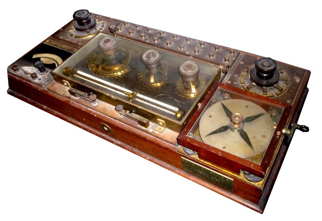
The instrument comprises the standard Tinsley DC potentiometer of the time, with a phase shifter, Weston dynamometer voltmeter, selection and change-over switches and terminal panels for connection of galvanometers, DC and AC measuring and supply voltages. Measures voltage as magnitude and phase from reference voltage.
Monash University, Department of Electrical and Computer Systems Engineering of Australia describes this machine as “Possibly the most technically significant or the measuring instruments” in their Graham Beard Memorial Collection. Massachusetts Institute of Technology, Boston in its reports of the President and Treasurer dated January 1913 states THE ALTERNATING CURRENT POTENTIOMETER. The rotor has a winding on it which supplies the potentiometer current. A rotation of the rotor of the phase-shifting transformer through 360o has the effect of producing a phase shift of the same value, and a pointer on the rotor axis indicates the phase angle on a suitably divided scale. The "balance" is obtained by successive approximation of the usual adjustment of the potentiometer contacts (dial and slide wire reading) and of the phase-shifting transformer until the indicator shows no deflection. The indicator for low frequencies is a vibration galvanometer which must be closely tuned to resonate to the frequency of the circuit. For higher frequencies a telephone may be used. The main potentiometer current must be kept at some known constant value. This is done by switching it over on to a continuous current circuit, which is adjusted until a balance is obtained at the proper setting, when a Weston cell is connected up in the usual manner. The reading of a sensitive dynamometer type ammeter in the main circuit is noted. This ammeter must read correctly with alternating and continuous currents. The potentiometer is then thrown on to the A.C. supply, which is adjusted so that the ammeter reads the same value. Arrangements are provided for reversing the ammeter in order to eliminate the effect of stray fields. The phase-shifting transformer is usually supplied by single-phase current. To obtain the necessary field distribution a split-phase scheme is used, part of the excitation being provided by a circuit containing a condenser and a resistance in series. These are adjusted until the A.C. current in the potentiometer circuit is as nearly constant as possible, when the phase-shifting transformer is rotated to any position. As it is necessary to have the splitphase circuit somewhere near the resonating point, it must be adjusted for changes of frequency. As the vibration galvanometer has also to be adjusted for such changes, it is necessary to have a source of a very steady frequency and voltage for satisfactory working. From Sir Richard Glazebrook’s 1922 publication see http://www.archive.org/details/dictionaryofappl02glazrich for details. Further references can be found at: http://www.archive.org/details/propagationofele030887mbp http://www.archive.org/stream/propagationofele030887mbp/propagationofele030887mbp_djvu.txt We are extremely grateful for the very kind donation from Rosemary Helme of this Drysdale Alternating and Continuous Current Potentiometer Date : 1909Manufacturer : Tinsley This exhibit has a reference ID of CH6538. Please quote this reference ID in any communication with the Centre for Computing History. |
 Click on the Image For Detail
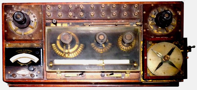 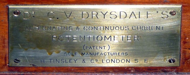   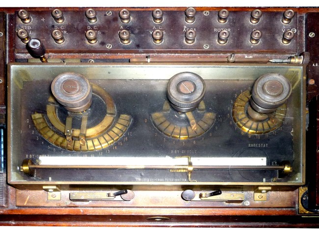 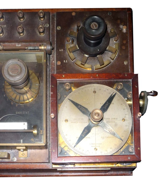 |