|
20th October 2021
Building the Virtual version of the LEO I installation at Cadby Hall has involved a lot of research, particularly with photographs and analysing minute detail on old grainy black and white photographs. Sometimes however, research has led us to potential sources of information well away from the archive's set of photographs.
The story of LEO computers eventually combined with the fortunes of English Electric, who will then be absorbed by International Computers Limited (ICL) and them by Fujitsu in 2002. ICL had gathered a collection of materials relating to this history and the story of computing in the UK. This 'ICL Collection' has found itself part of the Science Museum and stored at the National Collections Centre (NCC) in Wiltshire.
The ICL collection contains a wide range of materials covering many years of change but included a few references to Lyons and LEO. In particular, was an item relating to material collected by John Pinkerton and described as; 'Technical Drawings and two patent applications with drawings attached'. What could this be? Along with viewing some other references in the ICL collection, a visit to the NCC was enthusiastically undertaken.
You can find a description of the ICL collection here:
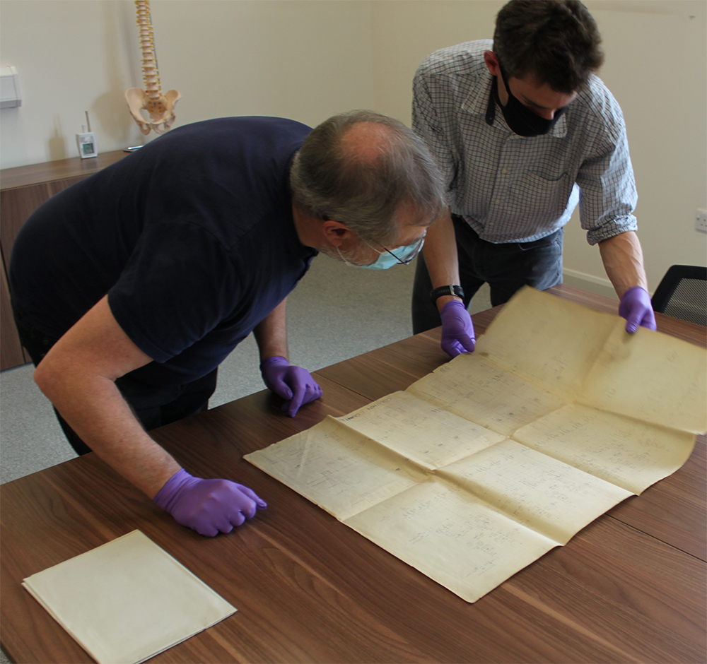
We found evidence at the NCC of potential use to the LEO VR project and then at the end of the day faced the last box, one containing the Pinkerton papers. The patent applications were in themselves interesting and perhaps worthy of a story at a later date. However, as we unfolded the first of the large 'Technical Drawings' there was no expectation that what would appear would be the first of many electronic circuit diagrams detailing the electronics that lay behind the building of LEO I.
This was one of those spine-tingling moments that revealed more and more. Altogether the box contained 54 circuit diagrams and several others detailing the construction of the mercury delay lines. We did not think that the circuit diagrams for LEO I had survived and yet here they were.

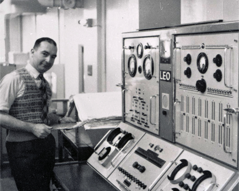
The images of LEO I presented in the PhotoApp had included several, (eg PhotoApp 101), that showed a set of large papers mounted on a triangular board next to the Engineer's console. We always suspected these were circuit diagrams and several accounts spoke of such documents being updated as changes were made.
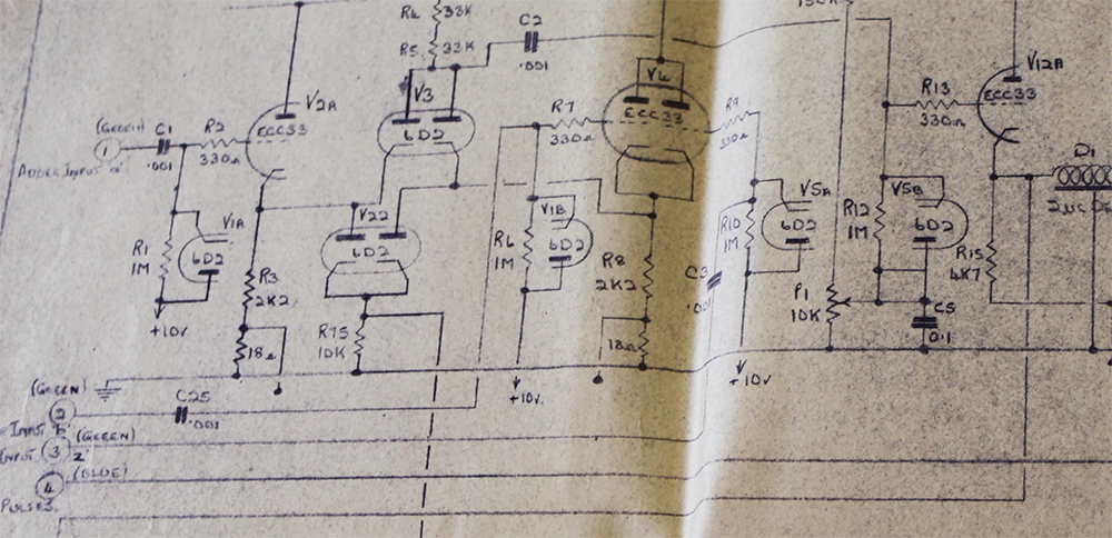
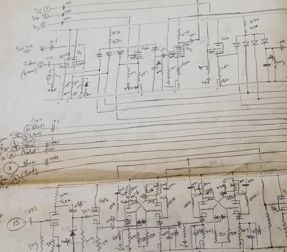
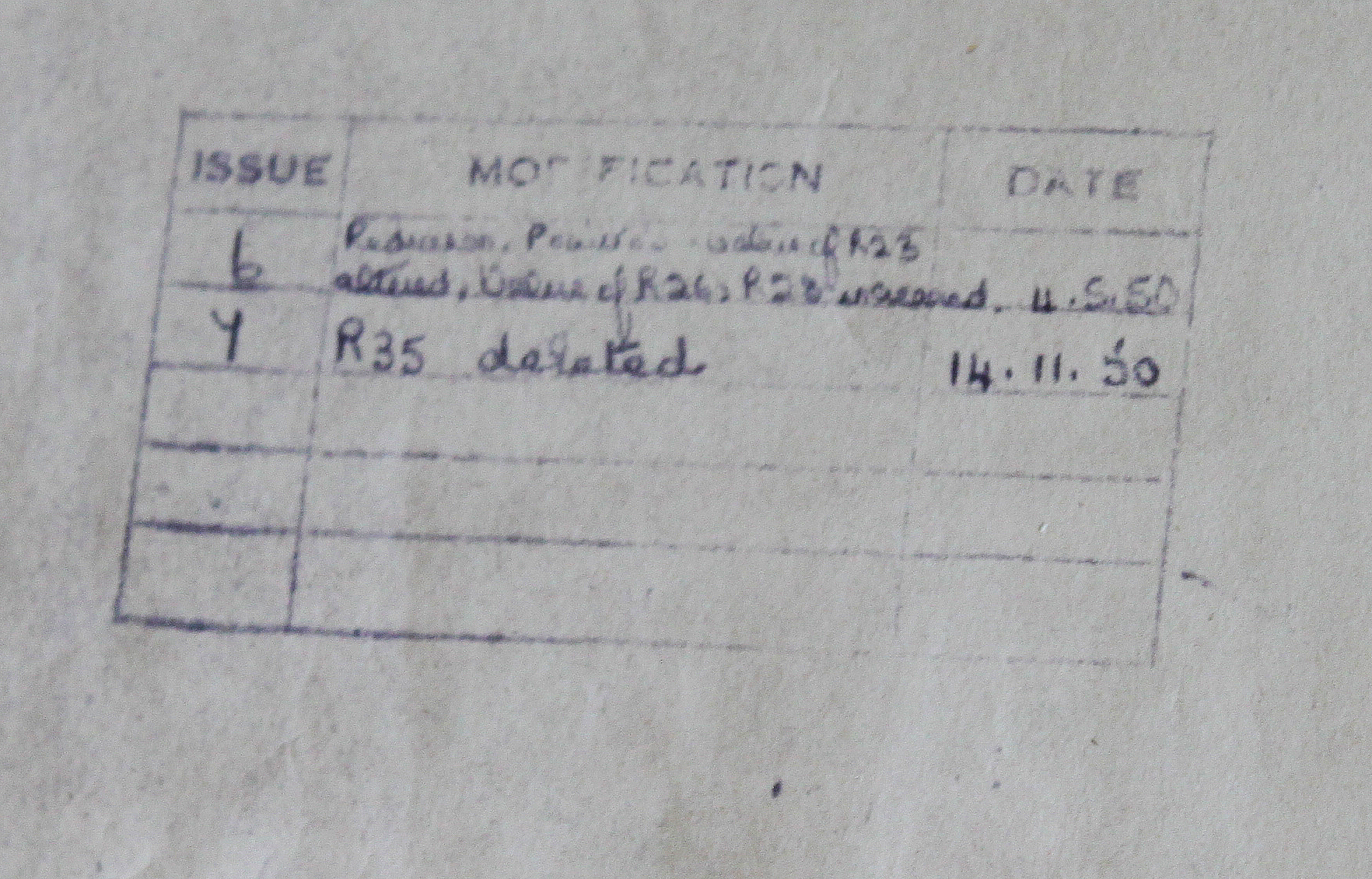
The diagrams we discovered at the NCC were in many cases edited, some extensively and by hand. Almost all recorded the fact that the particular circuit had been updated several times. They appeared to be 'working documents'.
Lyons had a 'drawing office dedicated to the production of technical diagrams in support of any work undertaken around the Cadby Hall site and not just LEO. It is further evidence of the facilities Lyons developed 'in-house' to service their wide variety of needs.
Curiously not long after, a similar item appeared in the online archives of the British Library and this again attracted a visit but this time to the excellent institution, the British Library's manuscripts department. Once again large technical drawings revealed LEO I circuit diagrams and these were sometimes copies of those at the NCC, new versions, or sometimes circuits not seen at the NCC.
John Pinkerton in his document 'A short description of the EDSAC type calculator circuits used in LEO' (Appendix 8)', listed the names of many of the circuits used by LEO I. Appendix 8 and the evidence from the NCC and the British Library has allowed us to build a list that probably covers most of the circuit and technical diagrams drawn to describe LEO I.
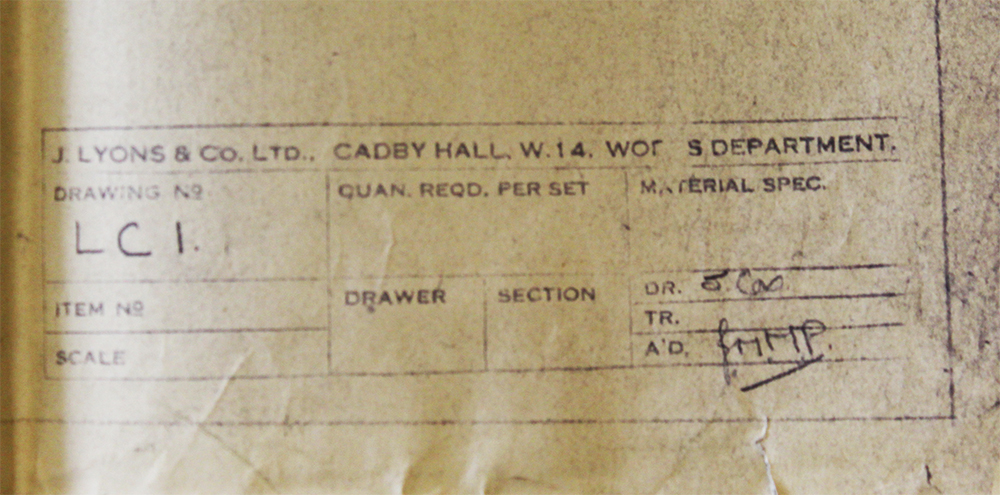
LEO I's electronic circuits were divided into modules that could be manufactured and slotted into the LEO racks. Each module was given a number, for example, LC43 A Pulse Selector. The list discovered to date is as follows;
LC1 Storage Unit
LC2 Clock Pulse Generator
LC3 Digit Pulse Generator
LC4 Frequency Control Unit
LC5 Unused
LC6 Decoder
LC7 Static Register
LC8 Unused
LC9 Co-ordinator Control I
LC10 Co-ordinator Control II
LC11 Co-ordinator Control III
LC12 Co-ordinator Control IV
LC14 Unused
LC15 Storage Junction Unit
LC16 Half Adder
LC17 Complementer
LC18 Unused
LC19 Timing Control Shifting Unit
LC20 Coder I
LC21 Coder II
LC22 Accumulator Shifting Unit I
LC23 Accumulator Shifting Unit II
LC24 Multiplicand Shifting Unit
LC25 Computer Control I
LC26 Computer Control II
LC27 Computer Control III
LC28 Computer Control IV
LC29 Computer Control V
LC30 Computer Control VI
LC31 Computer Control VII
LC32 Computer Control VIII
LC33 Collator and Mixer
LC34 Accumulator Warning and Computer Control Unit XI
LC35 Unused
LC36 Transfer Unit
LC37 Accumulator Input/Output Unit
LC38 Unused
LC39 Computer Control IX
LC40 Computer Control X
LC41 Unused
LC42 Pulse Selector Unit III
LC43 Pulse Selector Unit I
LC44 Pulse Selector Unit II
LC45 Coincidence Unit I
LC46 Coincidence Unit II
LC47 Changeover Unit
LC48 Primary Action Decoder
LC49 Computer Control XII
LC50 Clock and Digit Pulse Distributing Unit
LC51A Inlet Control 1A
LC51B Inlet Control 1B
LC52 Inlet Control II
LC53 Inlet Control III
LC55 Output Unit I
LC56 Output Unit II
LC57B Output & Time Scale Character Generator Part II
LC58 Operating Control Unit I
LC59 Operating Control Unit II
LC60A Outlet Annexe Control Unit IA
LC60B Outlet Control Unit 1B
LC61 Outlet Annexe Control Unit II
LC62 Outlet Annexe Control Unit III
LC63 Outlet Annexe Control Unit IV
LC70 Digit Reading Control
LC71 Information Handling Circuit
LC72 Tape Drive Control
LC73 Column Counter
LC74 Input Column Reading Control
LC75 Inlet Mixing Unit
LC76 Line Control
LC77 Line Column Counter
LC78A Output relay control unit
LC79 Perforator Control Unit
LC90 Conversion Constant Shifting Unit
LC96 Data Conversion Control Unit
LC208 Starter and Relay Unit
LC218 Programme Reader Control Circuit
Other technical documents
502 Computer (block diagram)
503 Coordinator (block diagram)
504 Coordinator Control Units (block diagram)
506 Input, Output & Operating Control (block diagram)
514 The Accumulator input channels (block diagram)
519 Computer Control block schematic (block diagram)
521 Typical circuits used in LEO - electronic circuits
LC750 The Minor cycle
18987 General arrangement of 16 tube mercury delay line battery - engineering diagram
18987/1 Guide plate & end block, crystal housing plate - engineering diagram
18987/2 Support bar, insulator, delay tube, insert, crystal clamping collar, main girder - engineering diagram
18987/3 Delay tube, trough, end screen, main girder - engineering diagram
18987/4 Drip chute, clamping washer, insulating washer, mercury seal, crystal seal, handle - engineering diagram
19074(1-3) Single tube mercury delay line
19074/2 Mercury tube, pillar, terminal plate, end screen, lock nut, attenuation screw - engineering diagram
19074/3 End plug, assembly sleeve, mercury seal, crystal seal, washer
Inlet Annex Control Units - one tube system
Inlet Annex Control Units - two tube system
Data & Result Conversion
Reconversion
Outlet Annex Block Schematic
Result Conversion Timing Chart
Spring Tabulation Cam Chart
Display Unit Type 2 & 3
We hope to include an example of the circuit diagrams in the LEO VR.
And, just as we thought this part of the story was complete, a similar item appears to be present in an archive at Manchester University. Another trip is planned and we wonder whether there is more to add to this part of the LEO story.
Posted by: Chris Monk
|